Description
Description
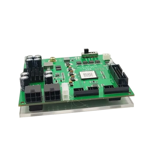
Avalon 8 9 10 test fixture / Avalon tester for A8 series / Avalon test stand
Avalon 8/9/10 Series Test Stand For testing Avalon miner A821 A841 A851 A852; A920 A921; A910 A911; A1066 A1047 (Note: A1066Pro cannot be tested with this fixture) hash board ASIC chip status, Help us find which area is the ASIC chip damage and find the problem more intuitively can fix the hash board accurately and quickly.
Please read the following introduction carefully before using this jig. Improper operation can easily cause the jig and hash board to burn out.
- White LED light: Indicates whether there is an output power supply; if the light is on, it means there is the output voltage, and if the light is not on, it means there is no output voltage.
- OUT+ (red clip): output positive, there are two voltages 10V and 12V, how much voltage is output is controlled by the mode switch. A8* and A9* series are both 10V output, and A10* series are 12V output; before the clip is connected to the board, be sure to confirm whether the model and model switch is switched correctly. OUT- (black clip): negative output pole.
- LED2 (green LED): Indicates that the board has passed the test and no maintenance is required.
- LED1 (red LED): indicates that the test board is not good and needs to be repaired; the specific problem still depends on the LOG, and some problems can be ignored.
- Gear switch: a total of 4 gears, the main output voltage is controlled by this switch.
The gear models are:First gear A841: A821 / A841 / A851 / A852
Second gear A920: A920 / A921
Third gear A911: A910 / A911
Fourth gear A10: A10 series (Note: A1066Pro cannot be tested with this fixture)
- White 2PIN interface, serial output of the first and second gears, pin 11 is GND (black cable), and pin 12 is RX (white cable).
- Yellow 2PIN interface, serial output of the third and fourth gears, pin 9 is GND (black cable), and pin 10 is RX (white cable).
- A10 IO: A10* data cable interface, connected to A10* data cable interface of hash board.
- Self-locking switch: Press this switch when you want to maintain and check the signal, the board signal (for example, the C signal will have a high level of one chip and a low level of the chip) will be output regularly, which is more convenient when measuring signals; normal test board When it is good or bad, this switch should be turned on, otherwise there will be no output from the serial port.
- A8-9 IO: The first and second gear data cable interface, connected to the A8*-A920/A921 hash board data cable interface after passing through the adapter board and the cable.
- A911 IO: The data cable interface of the third gear is connected to the data cable interface of the A910/A911 hash board after passing through the adapter board and the cable.
- PS_ON: Connected to the foot switch, press it to supply power immediately, release it to power off immediately. It is recommended that the continuous pressing time does not exceed 3 seconds. When the continuous pressing time reaches 6 seconds, the fixture will also automatically power off to prevent the hash board from overheating.
- IN(12V): The 12V output from the PC power supply is connected here to supply power to the fixture, and both interfaces must be connected well.
- Adapter board: A8*-A9* universal adapter board for cables, connected to the jig, and connected to the hash board via 2*7 cables. (Note: the colored side of the cable is connected to the first pin of the hash board)
Steps:
- The USB to the serial port is connected to the computer, and the fixture end is connected to the white or yellow interface according to the gear.
- Open the software to install the serial port driver; if it has been installed, you can ignore this step.
- Open the serial port software, select the corresponding COM* for the serial port number (you can view the serial port number in the device manager), and select the baud rate as 115200.
- Turn the switch to the corresponding position according to the model.
- The 6PIN output of the PC end is connected to the input port of the fixture.
- Connect the foot switch interface to PS_ON, and put the switch on the ground to control the power supply with a foot pedal.
- Connect the cable to the fixture according to the model.
- Connect the output power supply to the power supply of the hash board, first connect – and then +. (Note: If the positive and negative poles are reversed, it is easy to burn the jig and hash board)
- Connect the cable to the cable interface of the hash board. (According to experience, this step must be connected before stepping on the electricity)
- Step on the foot switch; the test result will be displayed in 2 seconds, one red/green LED will light up, and there will also be a Log display on the serial port software. After the test result comes out, release the foot switch (it is recommended that the continuous pressing time does not exceed 3 Seconds, when the jig is pressed continuously for 6 seconds, it will also automatically power off to prevent the hash board from overheating).
Problems that can easily lead to burning fixtures:
- The gear switch must be the correct model.
- The connection between the jig and the board must be correct, and cannot be misplaced or reversed.
- The board to be tested cannot have abnormal short circuit, and the main power supply can be measured with a multimeter; A10: Is the resistance value of the 6 data signals (DI, RI, CI, DO, RO.CO) of the data interface abnormal; A8-9 : Is the resistance value of 6 data signals (DI, RI, CI, DO, RO.CO) and 2 power supply (1.8V, 12V) of the data interface abnormal.


